Africa Exams
Where Preparation Meets Success
Home
Botswana
Botswana PSLE Papers
Botswana JCE Papers
Botswana BGCSE Papers
Ghana
Ghana BECE Exams
Kenya
Kenya KCPE Papers
Kenya KCSE Papers
Kenya KASNEB Papers
Nigeria
WAEC Exams
JAMB Exams
Rwanda
Rwanda Primary Papers
Rwanda Secondary Papers
Uganda
Uganda PLE Papers
Uganda UCE Papers
Uganda UACE Papers
Certifications
Technical
Cloud Tech Certifications
Security Tech Certifications
Management
IT Infrastructure
More
About
Contact Us
Our Apps
Privacy
+
-
Test Index
WAEC Computer Studies 2025 Paper
Show Para
Hide Para
Share question:
© africaexams.com
Question : 14
Total: 50
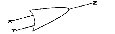
In Fig. 1, X, Y, and Z represent
output, output and input signals
output, input and output signals
input, output and input signals
input, input and output signals
Validate
Solution:
In the diagram labeled Fig. 1, X and Y represent the input variables, while Z represents the output variable. This indicates that the OR gate takes X and Y as inputs and produces Z as the output, based on the logical OR operation.
© africaexams.com
Go to Question:
1
2
3
4
5
6
7
8
9
10
11
12
13
14
15
16
17
18
19
20
21
22
23
24
25
26
27
28
29
30
31
32
33
34
35
36
37
38
39
40
41
42
43
44
45
46
47
48
49
50
Prev Question
Next Question